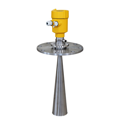
Home Products About us News Case FQA Download Contact us      
your position:home¡·products>metal tube rotameter
Catalogue
Electromagnetic Flowmeter
Vortex Flowmeter
Turbine Flowmeter
Ultrasonic Flowmeter
Metal Tube Rotameter
Level Meter
Orifice plate

Radar level Meter

Application£ºSolid particles, Powder
Measuring range:30 meters
Process connection:Thread, Flange
Temperature:-40¡æ ~ 250¡æ

Process pressure :-0.1 ~ 4.0MPa (Flat flange) /-0.1 ~ 0.1MPa (Universal Flange)

Accuracy: ¡À 10mm


Overview Technical data Inquiry

Product Overview

This series of radar level meter adopted 26G high frequency radar sensor, the maximum measurement range can reach up to 80 meters. Antenna is optimized further processing, the new fast microprocessors have higher speed and efficiency can be done signal analysis, the instrumentation can be used for reactor, solid silo and very complex measurement environment.

Principle

Radar level transmitter antenna microwave pulse is narrow, the downward transmission antenna. Microwave exposure to the medium surface is reflected back again by the antenna system receives, sends the signal to the electronic circuit automatically converted into level signals (because the microwave propagation speed, electromagnetic wave to reach the target and the reflected back to the receiver this time is almost instantaneous)
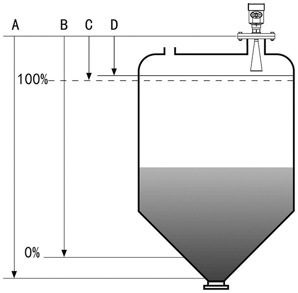
 

A :Range Set

B :Low Adjustment

C :High Adjustment

D :Blind Area

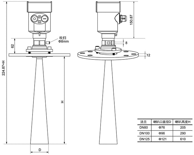
Datum measurement: Screw thread bottom or the sealing surface of the flange

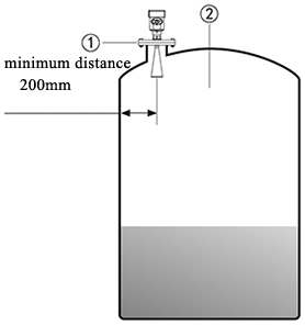
Note: Make sure the radar level meter the highest level cannot enter the measuring blind area (Figure D shown below).


Features

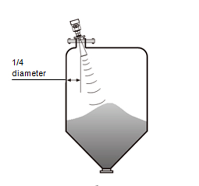
  1. Application Solid particles, Powder
    Measuring Range£º30 meters
    Process Connection£ºThread, Flange
    Medium Temperature£º-40¡æ ~ 250¡æ
    Process Pressure£º-0.1 ~ 4.0MPa (Flat flange)/-0.1 ~ 0.1MPa (Universal Flange)
    Accuracy£º¡À 10mm?
    Protection Grade£ºIP67
    Frequency Range£º26GHz
    Signal Output£º4... 20mA/HART (Two-wire / Four)/RS485/ Modbus
    Explosion-proof Grade£ºExia ¢òC?T6 Ga/ Exd ia ¢òC T6 Gb

Application


  • Solid particles, Powder

?Installation Requirements

Be installed in the diameter of the 1/4 or 1/6

Note: The minimum distance from the tank

wall should be 200mm

Note: ¢Ù datum .¢ÚThe container center or axis of symmetry


The top conical tank level, can be installed at

the top of the tank is intermediate, can guarantee

the measurement to the conical bottom

A feed antenna to the vertical alignment surface

If the surface is rough, stack angle must be used

to adjust the angle of cardan flange of the antenna

to the alignment surface

(Due to the solid surface tilt will cause the echo
attenuation, even Loss of signal.)

Typical installation errors

Conical tank cannot be installed above the feed port.

Note: outdoor installation should adopt sunshade

  1. Correct
  2. Error rainproof measures


The instrument cannot be installed in the arched or domed roof intermediate. In addition to produce indirect echo is also affected by the echoes. Multiple echo can be larger than the real value of signal echo, because through the top can concentrate multiple echo. So cannot be installed in a central location.

  1. Correct
  2. Error

There are obstacles affecting measurement needed reflection plate

  1. Correct
  2. Error


Production Process

Technical Parameters

The outer shell?

The seal between the shell and the shell cover?

Silicone rubber

Casing window Polycarbonate
The ground terminal Stainless steel

The power supply voltage

Two wire system The standard type/(16 ~ 26) V DC
Two wire system Intrinsically safe/(21.6 ~ 26.4) V DC


Power dissipation/max 22.5mA / 1W

Allowable ripple

- <100Hz Uss<lV

- (100¡«100K) Hz Uss<l0mV

The cable parameters

Cable entrance / plug 1 M20xl.5 cable entrance
 

1 blind plug

Terminal Conductor cross section 2.5mm2

Output parameters

The output signal (4 ~ 20) mA/RS485
   
Communication protocol HART
Resolution 1.6¦ÌA
Fault signal Constant current output; 20. 5mA
 

22mA


3.9mA

The integral time (0 ~ 50) s, adjustable
Blind area the ends of the antenna
The maximum distance measurement 80 meters
Communication interface HART communication protocol
Microwave frequency 26GHz
The measurement interval

about 1 second (depending on the parameter settings)

Adjust the time

about 1 second (depending on the parameter settings)

Display resolution

1 mm

Working storage and transportation temperature (-40¡«100) ¡æ
Process temperature (the temperature of the antenna part) (-40¡«250)¡æ
Pressure

Max.4MPa

Seismic Mechanical vibration l0m/s2, (10 ~ 150) Hz


SIZE


Project Case


Telephone:0086-18336316296

Email:mary.manager@kfkc-instrument.com,sales1_kfkc@126.com

Mobile Phone:0086-18336316296

Fax:0086-371-26669968

Address:3 Road, economic development area, Kaifeng City,Henan Province,China.


Copyright @ KFKC INSTRUMENT CO.,LTD